Model No. 10-H
*The 10-H series is a custom product.
To obtain pricing for the 10-H series, please fill out the following template with the required information listed below:
Visit the Quote Template page to download 10-H Quote Template (PDF)
1. Quantity of supports required (total footage of pipe)
2. Type of pipe
3. Size of pipe
4. Pipe contents
5. Center line distance between adjacent pipes for multiple pipe supports
6. Clearance height above roof
7. Thickness of any insulation around pipe
Downloads
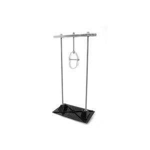
10-H
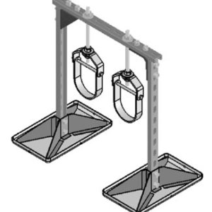
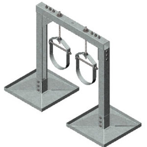
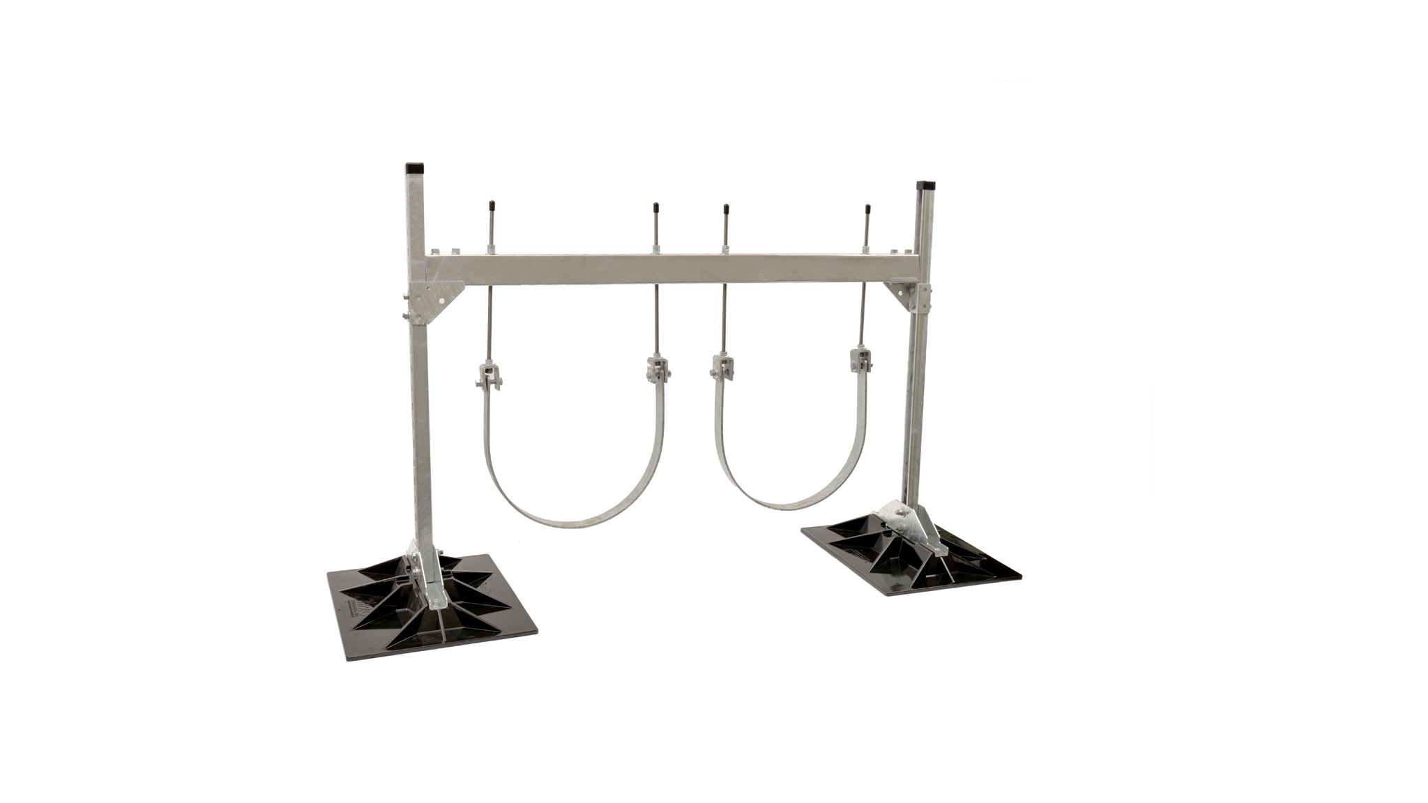
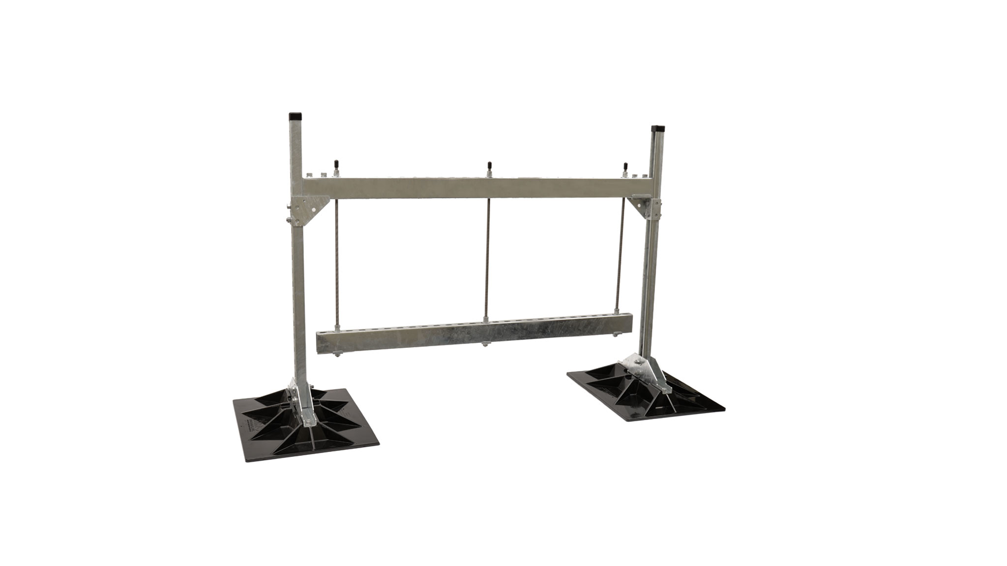
10-H Trapeze
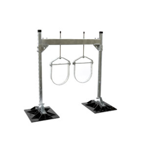
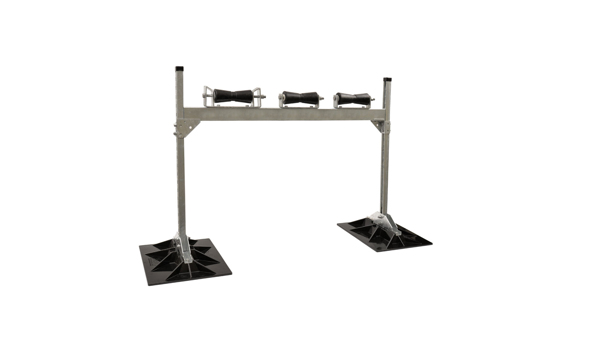
10-H 3 Roller Chair
Description
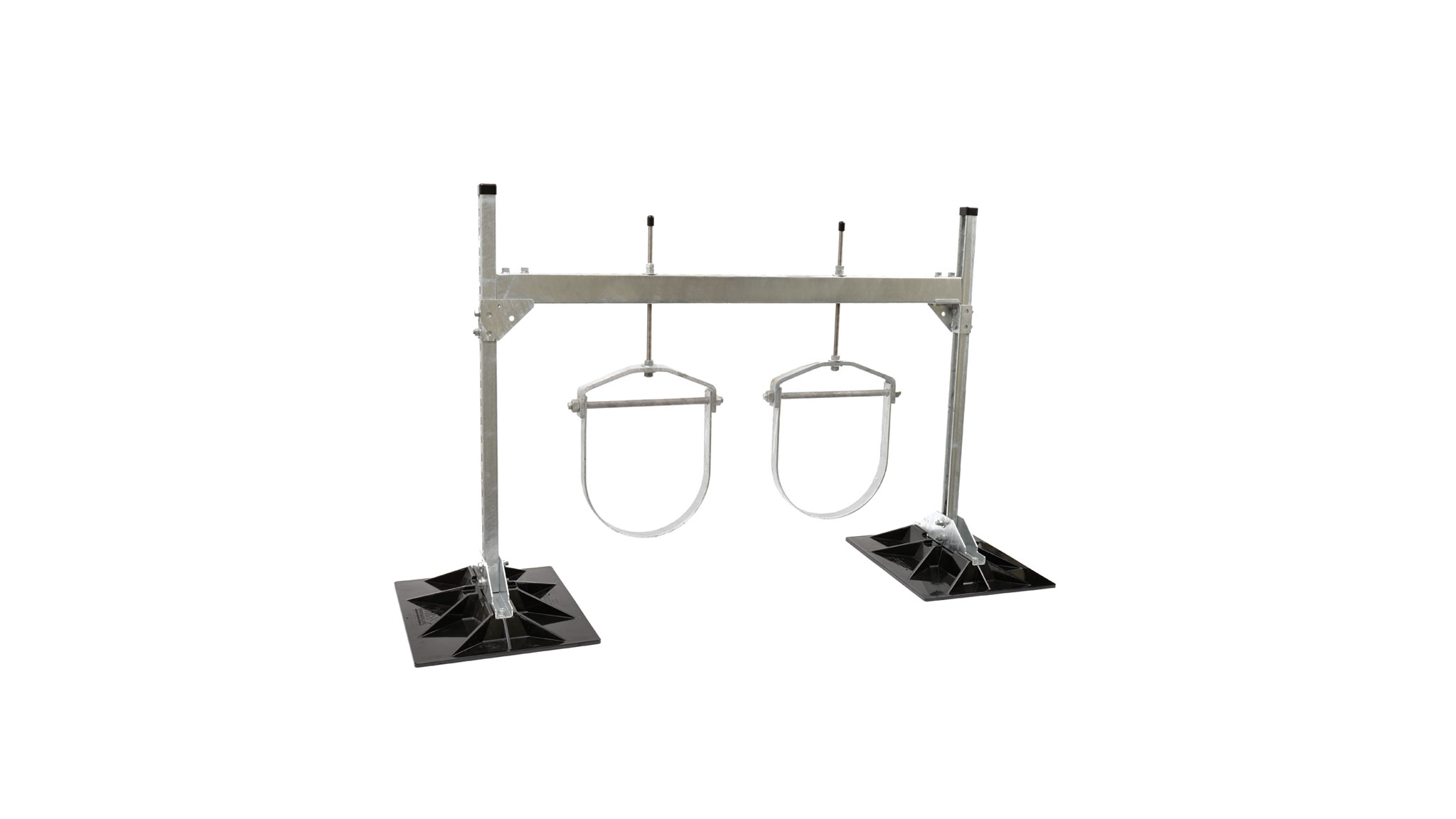
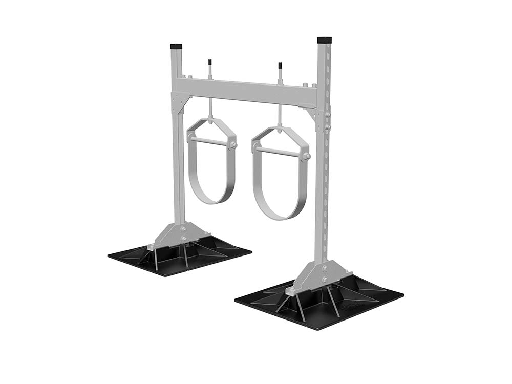
A “roller-bearing”, “clevis” and “trapeze” hanger pipe support hanger used to support roof mounted gas pipes,
HVAC piping, electrical conduit, solar piping and other mechanical piping. Unique design absorbs thermal expansion and contraction of pipes thus preventing damage to the roof membrane. Pipes rest on a polycarbonate or steel roller or a clevis or trapeze hanger. The pipe support base is made of polycarbonate resin. All other parts are hot-dip galvanized steel. Pipe stand will accommodate single or multiple pipe configurations with vertical adjustability.
| Base Material: | Polycarbonate |
| Size: | Each of the two deck bases are 19″ by 23″, and has a cradle width which allows at least 22″ between the strut assembly. |
| Max Pipe Size: | |
| Max Pipe Clearance: | The 10-H series and its related configurations allow adjustable height as desired or required by the code or roof system. Cross-bracing two adjacent pipe stands are required for elevations 36” and higher. Purchasers must specify desired heights and multiple pipe centerline spacing upon quote requests and ordering of 10-H series stands. |
| Max Load Weight: | The 10-H series support is engineered to ensure member/component capacities and deflection criteria are not exceeded. Maximum loading from any MIRO base to the finished roof surface is not to exceed 2.0 psi unless specifically allowed otherwise in the project specifications. Deflection in the horizontal header bar is not to exceed the span length divided by 360 or 1/8”. |
| Spacing: | Manufacturer’s recommended spacing is not to exceed 10 foot centers depending upon the load. Do not exceed specified load weight and make certain each pipestand is adjusted in height to even load at all pipestands. Support spacing is not to exceed the maximum spacing required in the pipe specifications where applicable. |